


Sagnac Effect: Interferometric Fiber Optic Gyroscope (I-FOG)
Tool Used: OptSim Circuit
The interferometric fiber-optic gyroscope (I-FOG) is today an important technology for many civilian and military applications such as inertial navigation and guidance systems for automotive, aircraft, and space industries; satellite antennas pointing and tracking; mining and tunneling operations; and helicopter attitude control. It brings the advantages of solid-state technology (guided-wave optics and low-voltage low-power electronics) with a cost reduction that enlarges the application domain.
The I-FOG is based on the Sagnac effect, which produces in a ring interferometer a phase difference proportional to the dot product of the rotation rate vector by the area vector enclosed by the optical path, and takes advantage of single-mode optical fiber as the propagation medium. Several critical system components and design characteristics affect the I-FOG performance: the coil optical fiber; the active source; the passive and integrated-optics components; the optical circuit configuration for reciprocity; and the detection schemes.
In this application, we demonstrate the design of an I-FOG using OptSim Circuit. Figure 1 illustrates the schematic. The system can be divided into three main sections: the source, the I-FOG fiber optic loop, and the signal detection.
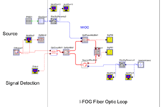
Figure 1. I-FOG layout using bidirectional Sagnac effect block.
Figure 2(a) illustrates the sweep of the rotation rate in the Sagnac effect block. Figure 2(b) shows the output of the detector section, illustrating the sinusoidal response due to the swept rotation rate. Finally, Fig. 2(c) shows a magnification of Fig. 2(b), highlighting the signal modulation.
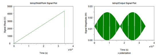
(a)
(b)
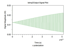
(c)
Figure 2. (a) Sweep of I-FOG rotation rate. (b) Output of detection section showing sinusoidal response. (c) Magnified portion of sinusoidal response showing signal