Optical Notch Filter PIC Using Cascaded Gratings
Tool Used: OptSim Circuit
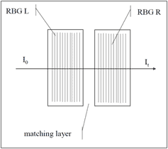
This application is based on the Reference [1]. Two identical reflective Bragg gratings are separated by a narrow gap as shown in Fig. 1.
The layout uses phase modulating component in the ring resonator structure as shown in Fig. 1.

Figure 1: Schematic layout of two reflective gratings
The filter with above arrangement will result in a narrow resonance due to reflections from both gratings. Traditional modeling tools for the fiber optic systems where signals are unidirectional won’t be able to model this phenomenon. On the other hand, OptSim Circuit is ideally suited for this type of modeling.
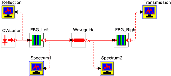
The OptSim Circuit layout for the PIC of Fig. 1 is shown in Fig. 2 below.

Figure 2: OptSim Circuit layout of two reflective gratings schematic of Fig. 1
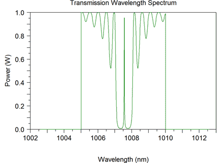
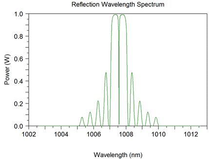
Figures 3 and 4 show transmission and reflection spectra respectively.

Figure 3: Transmission spectra due to the coherent combination of two reflecting Bragg gratings

Figure 4: Reflection spectra due to the coherent combination of two reflecting Bragg gratings
References:
1 J. Lumeau, V. Smirnov, and L. B. Glebov, "Phase-shifted volume Bragg gratings in photo-thermo-refractive glass," Optical Components and Materials V, Proceedings of SPIE, vol. 6890, 2008.


