


Synopsys IP Technical Bulletin Article
Tradeoffs Between Combinational and Sequential Dividers
Arshid Syed, Sr. Corporate Applications Engineer, DesignWare IP
I. Abstract
Use of floating-point blocks in different applications has increased due to the reduction of manufacturing costs and ease of use (software support). The floating point divider is one of the most complicated logic blocks in arithmetic intensive digital designs. This paper discusses the different types of dividers with an emphasis on floating point sequential dividers. Performance comparisons (area and delay) of combinational and sequential dividers are presented.II. Overview of Dividers
Arithmetic content in today’s designs has increased significantly, with the advancement of high speed and high performance applications like graphics/video, multimedia, digital signal processing (DSP), cryptography, and error correction. These designs span many industries, including computer, consumer, wireless communication, and networking. The size of arithmetic (datapath) solutions may vary in different applications, but their performance still significantly impacts overall chip performance. Datapath may contain simple adders, subtractors, multipliers, dividers and/or complex arithmetic expressions.Example:
1) Calculation of pixel coordinates and transformations in 3D-Graphics requires the following arithmetic calculations:
Consider a point with (x, y, z) coordinates.
Then, the length of the vector (from origin) is:
l = √ x2 + y2 + z2
To implement the above expression, 3 multipliers, 2 adders and a square root function are required.
Further examination shows that dividers come into the picture to calculate the unit vector, each co-ordinate is divided by the vector length x/l, y/l and z/l.
Example:
2) Consider calculations of 3D objects, like intersection of objects, where inverse of matrices are used. To get an inverse of a matrix, the determinant is calculated by adders and multipliers, and then all the elements of the transposed matrix are divided by the determinant. Hence the use of arithmetic operations in 3D graphic applications is extensive.
| P = |
|
, then inverse of P is 1/determinant [transpose of P] |
Number Representation:
Based on the representation of numbers, arithmetic circuits are divided into Fixed-Point and Floating-Point.
- Fixed-Point: numbers are represented as “x” number of integer bits and “y” number of fractional bits and every number has a fixed position of the decimal point. Integer operations are special cases of Fixed-Point operation without a fractional part.
- Floating-Point: real numbers are used, which are composed of two main parts: significand and exponent. The significand (also called mantissa) represents a fixed-point fractional value with a given number of bits.
| Sign | 8-bit Based Exponent | 23-Bit Normalized Fraction |
| [ 31] | [ 30 : 23 ] | [22:0] |
The following table lists several differences between representations:
| Fixed Point Arithmetic | Floating-Point Arithmetic |
| Simple circuit | Complex circuit (due to rounding and normalization) |
| Small area and faster, thus suitable for volume production | Large area and slower. It used to be suitable to low volume production. But with the advancement of technology, production costs are down. |
| Less accurate (the result is truncated if it exceeds the size) | More accurate (high precision) |
| Smaller range of values can be handled | Wider range of values can be handled |
The objective of this paper is to explore different divider types which can be effectively used in datapath designs. Among basic arithmetic operations, division is the most complex to implement due to its iterative nature. Quotient digit selection, overflow conditions, division by zero, shifts and subtract operation, contribute to the complexity of the dividers. Apart from complexity, dividers consume more area and introduce delay, making the design bigger and slower.
Performance of Arithmetic Circuits
Delay, Area and Power are used to evaluate the performance of arithmetic circuits.
One of the other quantitative measurements of performance of arithmetic circuits is “throughput”. In general, throughput is million operations executed per second (MOPS), which is 1000/delay in nano seconds.
III. Types of Dividers
The dividers can be categorized as combinational and sequential.
Combinational Divider
This is a basic divider in which the outputs (quotient and reminder) are the function of current inputs only. In combinational dividers (both fixed and floating point), the successive division operations start only after the preceding division operation is completed as shown in the Fig 1:
First division operation Second division operation
Figure 1: Floating Point Combinational Divider
There are many ways to implement a combinational divider, as described in academic textbooks. Dividers can be implemented by shifting and subtracting. One of the common algorithms used for division is Newton-Raphson method and digit-recurrence methods.
The combinational divider is generally constructed with a series of carry propagation adders (CPA). Thus, the size and especially the propagation delay increases non-linearly with the width of the operands (as the operand width increases, more and wider CPAs are used). So, when applying a stringent delay constraint, optimizing these cascading CPAs on the same combinational path is time-consuming and complex.
Due to the reasons mentioned above, combinational dividers may be suitable for designs where bit-width is smaller, typically around 16 bits or below. Throughput of combinational dividers drastically decreases with the increase in the bit-width of the operation. The other disadvantages of combinational dividers are, once designed; there is no user control to speed up the operation or reduce the area.
Sequential Divider
In this type of divider, the outputs (quotient and reminder) are the function of the current inputs and past inputs as well. This makes use of some storage elements (memory) and clocking to store the past inputs. Here the division is performed one bit per clock cycle (or sub-cycles). In these types of dividers, the partial reminders are stored and division is performed by successively subtracting a set of numbers, each being 0 or a shifted version of the divisor.
In sequential dividers (both fixed and floating point), the completion of division operation is based on the number of clock cycles configured for. Therefore, the throughput is 1000/ (delay * number of clock cycles), so as you increase the number of cycles, the delay is reduced, but not as much as the increase of number of clock cycles. So, the product of delay and number of clock cycles becomes large, which results in less throughput.
The advantages of the sequential divider are:
- It is smaller in area when compared with a combinational divider
- The designer has control over the number of cycles required to complete the operation. Thus, area and throughput can be controlled
The disadvantage of sequential dividers is that throughput becomes low as you increase the number of cycles to perform the division operation.
The basic diagram of a floating point sequential divider is shown in Fig 2:
 Figure 2: Floating Point Sequential Divider
The successive division operation starts only after the previous division operation is complete
as shown in Fig 3:
First division operation Second division operation
Figure 3: Floating Point Sequential Divider with 3 Cycles
Pipelined Divider
For repeated division operations, register pipelines can be inserted to provide increased throughput over combinational or sequential dividers. For example, if you have inserted 4 pipeline registers (called a 5-stage divider), it will have a latency of four clock cycles, which means that result of a division operation is available on the fifth clock cycle after the input values are clocked. However, because of its pipelined design, it can begin a new division operation on each clock cycle.
Based on the application and requirements, the number of pipelines can be built into the design.
First division operation Second division operation Third division operation
Figure 4: Floating Point Pipelined Divider with 3 Cycles
In summary, the following table compares these three types of dividers:
| Combinatorial Divider | Sequential Divider | Pipelined Divider |
| Basic divider designed with a series of carry propagation adders | Combinational divider is one of the sub-blocks | Combinational divider is one of the sub-blocks |
| Large area | Smaller area | Larger area |
| Large delay | Smaller delay | Smaller delay |
| Large throughput for smaller bit-width (< 16) | Small throughput | Gives maximum throughput |
| Runtime is higher for large bit-widths (>32) | Runtime is faster | Runtime is faster |
| Suitable for designs with smaller bit-widths and low speed designs where throughput is important | Suitable for area centric and low throughput designs. | Suitable for delay centric designs |
IV. DesignWare Dividers
DesignWare® Library has more than 160 technology-independent, high-quality, high-performance Building Block IP. The DesignWare Library Datapath and Building Block IP are tightly integrated into Design Compiler (DC) and are part of the DC installation. The Library has a number of arithmetic, combinational, sequential, and floating point components, and many other blocks such as FIFOs.
There are a number of different types of dividers available in DesignWare Library:
DW_div (Combinational Integer Divider): has configurable bit-width, supports signed and unsigned operation and it can be inferable using function call.
DW_div_pipe (Pipelined Divider): The widths of the operands and number of pipeline stages are parameterizable in this divider, and it supports both signed and unsigned operation. Automatic pipeline retiming ensures optimal placement of pipeline registers within the divider to achieve maximum throughput. Also, it has parameterizable stall and reset modes.
DW_div_seq (Sequential Divider): The widths of the operands and number of clock cycles are parameterizable and it supports both signed and unsigned data operation. Also, it has parameterizable registered input /output mode and reset mode.
DW_fp_div (Combinational Floating Point Divider): The precision format is parameterizable for either IEEE single, double precision, or a user-defined custom format, accuracy conforms to IEEE 754 Floating Point standard.
DW_fp_div_seq (Floating Point Sequential Divider): The precision is parameterizable for either IEEE single, double precision, or a user-defined custom format. Accuracy conforms to IEEE 754 Floating Point standard, parameterized number of clock cycles, registered or un-registered input and outputs, internal register for the partial pipelining.
Data sheets for all the above components are available at: http://www.synopsys.com/dw/buildingblock.php
V. DesignWare Floating Point Sequential Divider (DW_div_fp_seq):
As mentioned earlier, division operations are more complex and have bigger area and longer delay when compared with other basic operations like addition or multiplication.
The combinational floating point divider DW_fp_div, which uses combinational divider (DW_div) as its basic block, has similar issues of large area and long delays, making it unsuitable for applications where area is critical.
The DesignWare Library floating point sequential divider, DW_fp_div_seq, is suitable for low area and high frequency applications. The final division result of DW_fp_div_seq is same as DW_fp_div, but consumes less area.
The following are the features of DW_fp_div_seq:
- Parameterized precision, 32-bit (single), 64-bit (double) or user-defined custom format
- Support for IEEE 754 standard
- Parameterized number of clock cycles
- Parameterized registered or un-registered input and outputs
- Parameterized internal register for the partial pipelining
- Parameterized early start
- Datapath generator technology (context driven hybrid structures) is used for better area and delay.
- Area and delay can be improved if the component is hard coded to the desired rounding mode input. For example, RND input is tied to (3’b001) if user wants IEEE round to zero.
|

There are three parameters that control the registers. input_mode and output_mode place the input and output registers. early_mode makes a bypass from the input of the input register to the output of the input register. internal_reg enables the partial pipeline operation. Since the integer sequential divider consumes multiple clock cycles, the input data cannot be pipelined during the operation of the integer sequential divider. Once the integer sequential divider finishes the operation and passes the result to the normalization block, it can receive the next data from the input.
 Figure 6: Simulation waveforms of DW_fp_div_seq with the following parameters (Input/output_mode = 0, early_start = 0, internal_reg = 1 and num_cyc = 5) |
Area and delay for combinational vs. sequential dividers (DW_fp_div vs DW_fp_div_seq)
To evaluate the advantages and disadvantages of sequential dividers versus combinational floating point dividers, a performance bench mark has been done. The area and delay performance depends on the context, constraints, and technology library. Note that the following data is derived from the simple instantiation of the components, so results could be different (possibly better) when components are used in the actual design.
The following is the recommended methodology for synthesizing DesignWare Components:
// search path setup target
// link and technology library setup
// read_verilog ./instantiation.v
// delay constraints
// area constraints
compile_ultra
compile –incr
// reports and netlist generation
The benchmark was done with 2007.03-SP4 version of DC with TSMC 90nm library. The X and Y-axis represents delay in (ns) and area (lib area) respectively. The following curves are generated with several successive timing constraints with minimum area constraint.
 |
| Figure 7 - Area vs. Delay of DW_fp_div (bit-width = 16) |
Fig 7 shows the performance of 16-bit floating point combinational divider DW_fp_div. Notice the sharp increase in the area as you go below 10 ns delay.
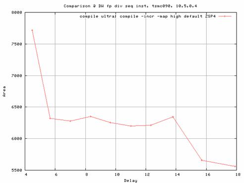 |
| Figure 8 - Area vs. Delay of DW_fp_div_seq (bit-width = 16, num_cyc = 4) |
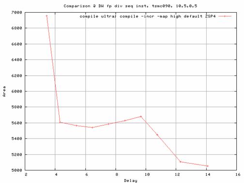 |
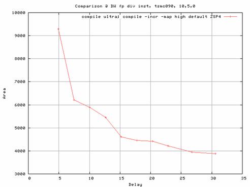
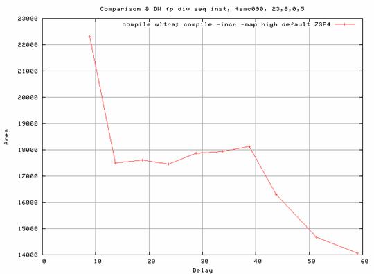
| Figure 9 - Area vs. Delay of DW_fp_div_seq (bit-width = 16, num_cyc = 5) |
Fig 8 & 9 shows the performance of 16-bit floating point sequential divider, DW_fp_div_seq, with num_cycles 4 and 5 respectively. Notice that the area is around 30% less for smaller delays when compared with the combinational divider. Thus, it gives additional control over area by using the num_cycles parameter.
The following figures compare the DW_fp_div, and DW_fp_div_seq with 32-bit operands and different num_cyc values.
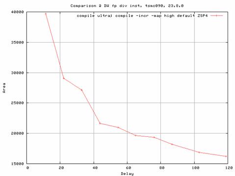 |
| Figure 10 - Area vs. Delay of DW_fp_div (bit-width = 32) |
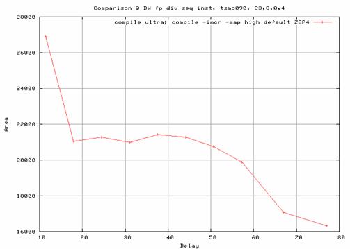 |
| Figure 11 - Area vs. Delay of DW_fp_div_seq (bit-width = 32, num_cyc = 4) |
 |
| Figure 12 - Area vs. Delay of DW_fp_div_seq (bit-width = 32, num_cyc = 5) |
VI. Conclusion
Of all the arithmetic operations, division is one of the most complicated and it often ends up in the critical path of many designs. Dividers can be implemented in a variety of ways as previously explained. Combinational dividers are useful for smaller bit-widths and lower frequency designs. For area centric and high frequency designs sequential dividers are most suitable.