


Synopsys IP Technical Bulletin Article
Using DW_ahb_dmac in an AXI Subsystem
Introduction
The AHB DMA Controller (DW_ahb_dmac) can be used in an AHB subsystem to perform DMA transfers between AHB peripherals. When the AHB subsystem is bridged to an AXI subsystem through a combination of DW_ahb_eh2h and DW_axi_hmx, it is possible to do DMA transfers between AHB and AXI peripherals.
To learn how to connect an AHB subsystem to an AXI subsystem (using a combination of DW_ahb_eh2h and DW_axi_hmx), refer to the application note, Connecting an AMBA 2.0 AHB Subsystem to an AMBA 3 AXI Subsystem.
For transfers between AXI peripherals, the DW_ahb_dmac can be connected directly to an AXI subsystem.This application note describes how to connect DW_ahb_dmac to an AXI subsystem to allow DMA transfers between AXI peripherals. It describes how to use Synopsys coreAssembler to integrate multiple DesignWare Synthesizable IP, as well as how to incorporate non-DesignWare IP into a subsystem. Finally, it discusses various integration considerations, including how to configure DesignWare Synthesizable IP used in this type of subsystem.
All DesignWare components used in this application note, as well as coreAssembler usage, are made available via a standard DesignWare license.
System Block Diagram Examples
Figures 1 and 2 illustrate the use of the DMA controller (DW_ahb_dmac) in two different AXI subsystem configurations.
Subsystem Example 1
Figure 1 illustrates a subsystem configured with DW_ahb_dmac on an AXI bus and using DW_axi_x2h and DW_axi_hmx components. In this case, DW_ahb_dmac is being programmed from an AXI master through an AXI-to-AHB bridge.
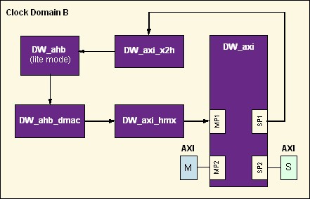
Figure 1: DW_ahb_dmac in an AXI Subsystem using DW_axi_x2h and DW_axi_hmx
The components in this subsystem configuration are:
| AXI Master (M) | A component that generates new transactions to AXI slaves (for example, a microprocessor) |
| AXI Interconnect (DW_axi) | DesignWare Synthesizable IP component that routes AXI requests/responses between AXI masters and AXI slaves |
| AXI-to-AHB Bridge (DW_axi_x2h) | DesignWare Synthesizable IP component that processes AXI requests, translates them to the AHB bus and returns the AHB response to the AXI response channels |
| AHB Interconnect (DW_ahb) | DesignWare Synthesizable IP component that is responsible for AHB bus arbitration, address decoding and data multiplexing between AHB masters and AHB slaves |
| AHB DMA Controller (DW_ahb_dmac) | DesignWare Synthesizable IP component that transfers data from a source peripheral to a destination peripheral over one or more AHB bus |
| AHB-to-AXI Gasket (DW_axi_hmx) | DesignWare Synthesizable IP component that connects an AHB master to an AXI Subsystem |
| AXI Slave (S) | A component that responds to transactions from AXI masters |
Subsystem Example 2
Figure 2 illustrates a subsystem in which DW_ahb_dmac connects to an AXI interconnect through the DW_axi_hmx. In this case, DW_ahb_dmac is being programmed from an AHB master through an AHB subsystem.
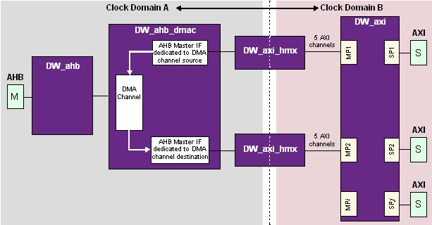
Figure 2. DW_ahb_dmac connected in an AXI subsystem using DW_axi_hmx
This example uses two dedicated AXI master interfaces, one for the source peripheral and the other for the destination peripheral, to obtain higher DMA performance.
The components in this subsystem are:
| AHB Master | A component that generates transactions to AHB slaves |
| AHB Interconnect (DW_ahb) | DesignWare Synthesizable IP component that is responsible for AHB bus arbitration, address decoding and data multiplexing between AHB masters and AHB slaves |
| AHB DMA Controller (DW_ahb_dmac) | DesignWare Synthesizable IP component that transfers data from a source peripheral to a destination peripheral over one or more AHB bus |
| AHb-to-AXI Gasket (DW_axi_hmx) | DesignWare Synthesizable IP component that connects an AHB master to an AXI Subsystem |
| AXI Interconnect (DW_axi) | DesignWare Synthesizable IP component that routes AXI requests/responses between AXI masters and AXI slaves |
| AXI Slave | A component that responds to transactions from AXI masters |
NOTE - Clock domains A and B have to be synchronous to each other in this case. For asynchronous clocks, refer to the application note Connecting an AMBA 2.0 AHB Subsystem to an AMBA 3 AXI Subsystem.
Creating the Subsystem
When you use the Synopsys coreAssembler tool with DesignWare Synthesizable IP, you can construct and simulate any conceivable single- or multi-layer AMBA-based subsystem. coreAssembler is a highly flexible, integrated and feature-rich design environment that allows you to select, configure, interconnect, simulate, and synthesize IP. This application note describes the specific coreAssembler steps to connect DW_ahb_dmac to an AXI subystem as illustrated in Figure 2 above. .
Required Tools, Components and Licenses
- DW_ahb
- DW_ahb_dmac
- DW_axi_hmx
- DW_axi
For detailed information about downloading and installing DesignWare Library Synthesizable IP, click here.
coreAssembler Steps
Once coreAssembler and DesignWare Library Synthesizable IP are installed on your system, you can start creating your subsystem. In coreAssembler, create a new workspace, then proceed as follows:
Add Subsystem Components and Interface Configuration
With any new coreAssembler workspace, you will see a blank schematic, an Activity List, and a console for text input/output. The first activity to complete in the Activity List is Add Subsystem Components:
- Insert components.
The minimum set of components required are DW_axi, DW_ahb, DW_ahb_dmac and 2 instances each of DW_axi_hmx. Use the menu item for : Schematic -> Add New Component.
- For each added component, right-click on each and use Edit Interface Parameters to verify the values of the parameters that affect that component’s interfaces. For DW_ahb_dmac, set DMAH_NUM_MASTER_INT, the number of AHB master interfaces, to 2.
- For each added component, right-click on each and use Change Connection to verify the interface connections are correct. Any interface marked in red must be connected or marked as unused. For the second DW_axi_hmx instance, connect its AHB master interface to DW_ahb_dmac’s master 2 interface.
- For any AHB masters, if you are not using a DesignWare Synthesizable IP for that component, you can use Export Interface. To do this, right-click on DW_ahb and choose Export Interface. In the dialogue that opens, make sure to select AHB Master from the component interface list. Export Interface creates top-level ports in your subsystem RTL for all signals in the interface, which you can then use to connect to the RTL for your AHB master RTL outside coreAssembler. Alternatively, with a coreAssembler license you can import your own IP RTL directly into coreAssembler using Import Component, and not use Export Interface.
Similarly, if any AXI slaves in your AXI subsystem are not DesignWare Synthesizable IP you can use Export Interface or Import Component for those, as well.
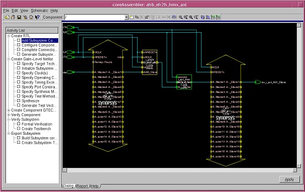
Figure 3: coreAssembler Example Subsystem
After completing these steps, click Apply in the lower right corner of the schematic. If you’ve configured a legal subsystem, the Add Subsystem Components activity will complete successfully. If the subsystem contains errors, correct those errors and click Apply again.
Configure Components
To move to the next activity in coreAssembler, click on Configure Components in the Activity List. For this activity, you will configure each individual component separately. For each component, if you are not sure what a specific configuration parameter controls, details on that parameter can be found in the databook for that component. The databook for every component in the subsystem is available from the Help menu. Another way to retrieve brief information on a parameter is to right-click on the parameter and choose What’s This? from the menu.
To complete this activity, click Apply in the lower right corner, or simply click on the next activity in the Activity List. When this activity completes, the RTL for each individual component, but not the top level of the subsystem, is written to the coreAssembler workspace directory.
Complete Connections
In the Complete Connections activity, you have the opportunity to manually connect/disconnect wires in the subsystem. Typically, no manual changes are required. Complete this activity by clicking Apply or clicking on the next activity in the Activity List.
Generate Subsystem RTL
This is the last activity in the Create RTL activity group. Choose the RTL language in which you want the top level RTL to be written, and click Apply to complete this activity. When this activity completes processing, the configured RTL for the entire subsystem has been written to the coreAssembler workspace.
Additional Optional Activities in coreAssembler
| Create Gate-Level Netlist | This activity group is used to synthesize the subsystem. Support is provided for Design Compiler, DFT Compiler, Power Compiler, Physical Compiler, PrimeTime (timing model generation), and TetraMax (ATPG). Licenses are required for each tool used. |
| Verify Component | For each DesignWare component, tests and component-specific testbenches are provided to demonstrate the functionality of the component. The tests and testbenches used in these activities are not reusable, however the simulation waveforms are useful to examine detailed signal behavior. |
| Verify Subsystem | The Formal Verification activity runs Formality (license required) on the entire synthesized subsystem. The Simulate Subsystem activity generates a custom testbench for your specific subsystem configuration and executes basic connectivity tests (also called "ping" tests). The testbench and tests created by this activity can be reused as a starter testbench for a larger subsystem or more detailed tests. |
| Create Component GTECH Simulation Model | If VCS is the simulator used for the Subsystem Simulation or Verify Component activities, this activity group is not required. However, if a simulator other than VCS is selected, and you don’t own a source license for the RTL of the DesignWare component, a GTECH simulation model is required and these activities must be completed before simulation can be run. |
| Export Subsystem | If you intend to package the subsystem for re-use in different designs, or to package your own subsystem IP for delivery to your customers, these activities can be used. They require a coreBuilder license. For more information, see the coreBuilder User Guide. |
Integration Considerations
When integrating multiple DesignWare IP components, much of the detail is handled automatically by coreAssembler:
- Component inputs/outputs that belong to standard interfaces (for example, the AXI protocol) are connected automatically.
- Component inputs/outputs that do not belong to standard interfaces (for example, interrupt pins) are automatically handled with default connections that are pre-defined by the DesignWare IP designer.
- Interface parameters (for example, AXI address bus width or AHB data bus width) are defined one time, and then propagated to connected components automatically.
- Configured RTL generation for both components and the top level of the subsystem occurs automatically.
- Subsystem-level synthesis and verification are highly automated.
Performance/ Area Trade-off
Depending on system requirements, you can configure and connect DMA controller(s) to the ports of DW_axi via DW_axi_hmx modules with a tradeoff between area and performance.
Let’s take an example where a system requires four parallel DMA operations, i.e., 4 parallel DMA channels are required.
Highest Performance
Configuring the subsystem to achieve the highest performance requires the following components:
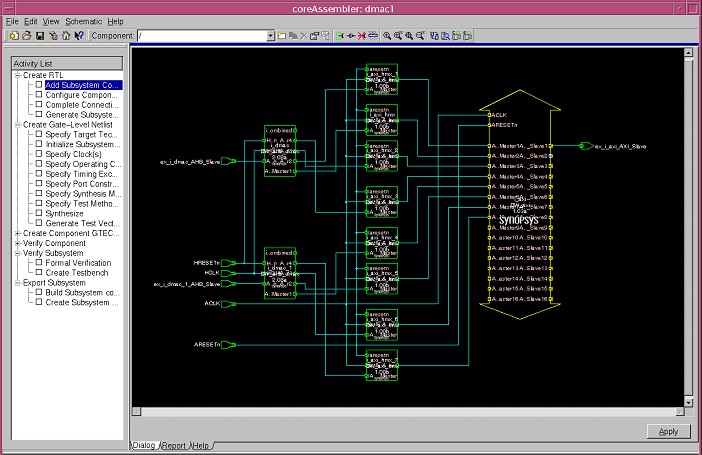
Figure 4: Subsystem Configuration for Highest Performance (Highest Area)
The setup for the highest performance configuration is as follows:
1. Configure two DMA Controllers - Each DMA Controller has two channels and four master interfaces.
- There are four DMA channels: DMA1_CH1, DMA1_CH2, DMA2_CH1 and DMA2_CH2, where DMA1 is the first DMA controller and DMA2 is the second DMA controller.
- There is a total of eight DMA master interfaces, four on each DMA, DMA1_M1, DMA1_M2, DMA1_M3, DMA1_M4 on first DMA controller, DMA2_M1, DMA2_M2, DMA2_M3 and DMA2_M4 on the second DMA controller.
Configure the DMA channels and master interfaces as follows:
| Source | DMA1_CH1 <-> DMA1_M1 |
| Destination | DMA1_CH1 <-> DMA1_M2 |
| Source | DMA1_CH2 <-> DMA1_M3 |
| Destination | DMA1_CH2 <-> DMA1_M4 |
| Source | DMA2_CH1 <-> DMA2_M1 |
| Destination | DMA2_CH1 <-> DMA2_M2 |
| Source | DMA2_CH2 <-> DMA2_M3 |
| Destination | DMA2_CH2 <-> DMA2_M4 |
2. All eight DMA master interfaces have a DW_axi_hmx in front of them.
This setup allows:
(a) Four outstanding read commands
(b) Four outstanding write commands
(c) Read data and write data interleaving between channels
(d) Separate read and write command channels
Lowest Area
Configuring the subsystem for lowest area requires the following components:
- Single, four-channel four-AHB-master interface DMA Controller
- Four DW_axi_hmx interface modules
- Four DW_axi ports
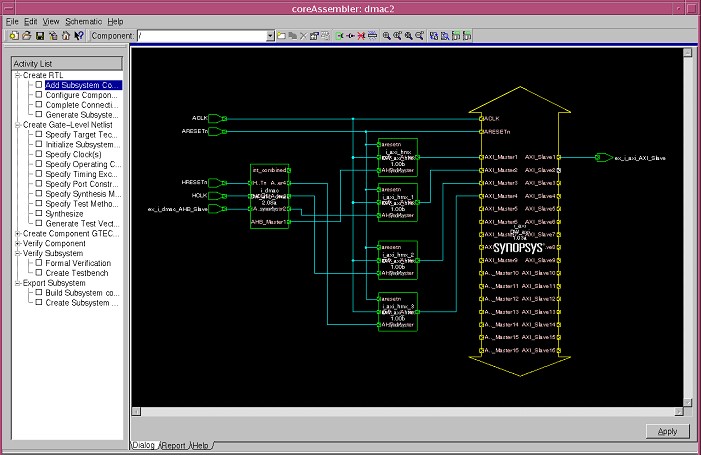
Figure 5: Subsystem Configuration for Lowest Area (Lowest Performance)
The setup for the lowest area configuration is as follows:
- The Four DMA channels are DMA1_CH1, DMA1_CH2, DMA1_CH3 and DMA1_CH4
- There are four DMA master interfaces: DMA1_M1, DMA1_M2, DMA1_M3 and DMA1_M4.
Configure the DMA channels and interfaces as follows:
| Source | DMA1_CH1 <-> DMA1_M1 |
| Destination | DMA1_CH1 <-> DMA1_M2 |
| Source | DMA1_CH2 <-> DMA1_M1 |
| Destination | DMA1_CH2 <-> DMA1_M2 |
| Source | DMA2_CH3 <-> DMA1_M3 |
| Destination | DMA2_CH3 <-> DMA1_M4 |
| Source | DMA2_CH4 <-> DMA1_M3 |
| Destination | DMA2_CH4 <-> DMA1_M4 |
2. All four DMA master interfaces have an HMX in front of them.
This setup allows:
- Separation of read and write command and data channels.
- A possible read outstanding command depth of 2 if the read commands originate from different master interfaces, i.e. there can only be a single read active command between channels 3 and 4. However, there could be, for example, an active read command from DMA1_CH1 or DMA1_CH2, and DMA1_CH3 or DMA1_CH4.
- Possible read/data interleaving with the same restrictions as described in (b)
Defined-Length Burst Support on DMAC
DW_ahb_dmac supports incremental (INCR) bursts by default. For better performance, defined-length bursts, such as INCR4, INCR8 and INCR16, are required. There is a way by which DW_ahb_dmac can support defined-length bursts, please refer to the following Solvnet article for more details: https://solvnet.synopsys.com/retrieve/016033.html
Reference Documentation
The following documents can be found in the Guide to DesignWare AMBA IP Components Documentation. This document can also be found on your local system, upon installation of the DesignWare Synthesizable IP for AMBA, at $DESIGNWARE_HOME/doc/amba/latest/intro.pdf.
| DW_axi_hmx Databook and Release Notes | For detailed information on how commands are transferred from an AMBA 2.0 AHB master to AMBA 3 AXI Interconnect Fabric, refer Chapter 3 (Functional Description) and Chapter 7 (Integration Considerations)in the DW_axi_hmx databook. |
| DW_axi_x2h Databook and Release Notes | For detailed information on how commands are transferred from AXI to AHB, refer to Chapter 3 (Functional Description) and Chapter 7 (Integration Considerations)in the DW_axi_x2h databook. |
| DW_axi Databook and Release Notes | Provides AXI interconnect details |
| DW_ahb Databook and Release Notes | Provides AHB interconnect details. |
| DW_ahb_dmac Databook and Release Notes | Provides AHB DMA Controller details. |
| coreAssembler User Guide | Guide to general coreAssembler usage |