


Synopsys IP Technical Bulletin Article
Connecting an AMBA 2.0 AHB Subsystem to an AMBA 3 AXI Subystem
Introduction
With the transition of new designs to AMBA 3 AXI, there is considerable existing AMBA 2.0 AHB-based intellectual property (IP) which can continue to be very useful. To quickly integrate legacy AHB designs into AXI subsystems, without requiring time-consuming and risky re-design, Synopsys provides an efficient and reliable method of reuse.
The DW_axi_x2h provides a method to transfer AXI generated transactions to an AHB bus. It provides the subsystem designer with an easy way to reuse existing AHB components or full AHB subsystems in new designs that use the higher performance AXI bus.
For more details, please refer to application note Connecting an AMBA 2.0 AHB Slave to an AMBA 3 AXI Subsystem.
The DW_axi_hmx enables a single AHB master to be connected directly to an AXI bus. The focus of this application note is to show how you can connect an AHB-based subsystem to an AXI subsystem using DW_ahb_eh2h and DW_axi_hmx. So, a complete bridging solution using DesignWare Synthesizable IP is available between AHB and AXI subsystems.
This application note reviews the steps required to integrate multiple DesignWare Synthesizable IP using coreAssembler, as well as how to include non-DesignWare IP in the subsystem. Finally, it discusses various integration considerations, including how to configure DesignWare Synthesizable IP used in this type of subsystem.
All DesignWare components referenced in this application note, as well as the Synopsys coreAssembler, are made available with a standard DesignWare license.
Example System Block Diagram
Figure 1 illustrates a subsystem in which an AHB interconnect connects to an AXI interconnect using DW_ahb_eh2h and DW_axi_hmx. In this bridge solution, DW_ahb_eh2h performs the following functions:
- Downsizing of data for differing AHB/AXI data widths
- Support for synchronous or asynchronous clock domains
- Off-loading of the AHB bus when a transaction on the AXI bus is ongoing
and DW_axi_hmx performs the following functions: - Support for endianness conversion
- Protocol conversion
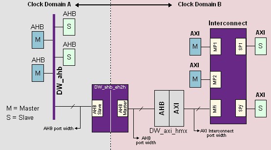
Figure 1: Example AHB-to-AXI Bridge
The components in this subsystem are:
AHB Master| A component that delivers new transactions to AHB slaves (for example, a microprocessor) | |
| AHB Interconnect (DW_ahb) | DesignWare Synthesizable IP component responsible for AHB bus arbitration, address decoding, and data muxing between AHB masters and AHB slaves |
| AHB-to-AHB Bridge (DW_ahb_eh2h) | DesignWare Synthesizable IP component that establishes a communication link between two AHB subsystems, allowing for data exchange between a primary master and a secondary slave. It is attached as a slave to first AHB subsystem and as a master to the second AHB subsystem. |
| AHB-to-AXI Gasket (DW_axi_hmx) | DesignWare Synthesizable IP component that connects an AHB master to an AXI subsystem |
| AXI Interconnect (DW_axi) | DesignWare Synthesizable IP component that routes AXI requests/responses between AXI masters and AXI slaves |
| AXI Slave | A component that responds to transactions from AXI masters |
Creating the Subsystem
The Synopsys coreAssembler tool is a highly flexible, integrated and feature-rich design environment that allows you to select, configure, interconnect, simulate, and synthesize IP. By using the coreAssembler tool with DesignWare Synthesizable IP, you can construct and simulate any single- or multi-layer AMBA-based subsystem.
This application note describes the coreAssembler steps required to connect an AHB-based subsystem to an AXI subsystem.
Required Tools, Components, and Licenses
Required tools, components and licenses are:
- coreAssembler 2006.03-SP1
- DesignWare Synthesizable IP for AMBA (more information)
- DW_axi
- DW_axi_hmx
- DW_ahb_eh2h
- DW_ahb
- DesignWare license
For detailed information about downloading and installing DesignWare Library Synthesizable IP, click here.
coreAssembler Steps
Once coreAssembler and DesignWare Library Synthesizable IP are installed on your system, you can start creating your subsystem. In coreAssembler, create a new workspace, then follow these instructions:
Add Subsystem Components and Interface Configuration
With any new coreAssembler workspace, you will see a blank schematic, an Activity List, and a console for text input/output. The first activity to complete in the Activity List is "Add Subsystem Components."
- Insert components
The minimum set of components required are DW_ahb, DW_axi_eh2h, DW_axi_hmx and DW_axi. Use the menu item for Schematic -> Add New Component.
- For each added component, right-click on each, and use Change Connection to verify the interface connections are correct. Any interface marked in red must be connected or marked as unused.
- For each added component, right-click on each and use Edit Interface Parameters to verify the values of the parameters that affect that component’s interfaces. Certain components (for example, DW_axi_eh2h) do not have any interface parameters that are configurable, since their interfaces are automatically configured based on how attached components (for example, DW_ahb and DW_axi_hmx) are configured.
- For any AHB master or AXI slave components that are not DesignWare Synthesizable IP, you can use Export Interface. You can export an AHB Master interface from DW_ahb and an AXI Slave interface from DW_axi. Export Interface creates top-level ports in your subsystem RTL for all signals in the interface, which you can then use to connect to the RTL for your AHB master and AXI slave RTL outside of the coreAssembler environment. Alternatively, with a coreAssembler license you can import your own IP RTL directly into coreAssembler using Import Component.
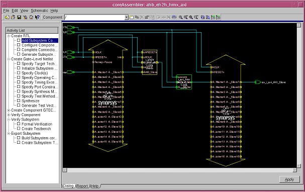
Figure 2: coreAssembler Example Subsystem
After completing these steps, click Apply in the lower right corner of the schematic. If you’ve configured a legal subsystem, the Add Subsystem Components activity will complete successfully. If the subsystem has errors, correct them and click Apply again.
Configure Components
The next step in coreAssembler is to click on Configure Components in the Activity List. For this activity, you will configure each individual component separately. For each component, if you are not sure what a specific configuration parameter controls, details can be found in the databook for that component. The databook for every component in the subsystem is available from the Help menu. Another way to retrieve brief information on a parameter is to right-click on the parameter and choose What’s This? from the menu.
Further discussion of specific configuration details for this subsystem are discussion in "Integration Considerations" later in this application note.
To complete this activity, click Apply in the lower right corner, or simply click on the next activity in the Activity List. When the activity is complete, the RTL for each individual component, but not for the top level of the subsystem, is written to the coreAssembler workspace directory.
Complete Connections
In the Complete Connections activity, you have the opportunity to manually connect/disconnect wires in the subsystem. Generally, no manual changes are required. Complete this activity by clicking Apply or click on the next activity in the Activity List.
Generate Subsystem RTL
This is the last activity in the Create RTL activity group. Choose the RTL language you want the top level RTL to be written in and click Apply to complete the activity. When this activity completes processing the configured RTL for the entire subsystem has been written to the coreAssembler workspace.
Additional Optional Activities in coreAssembler
| This activity group is used to synthesize the subsystem. Support is provided for Design Compiler, DFT Compiler, Power Compiler, Physical Compiler, PrimeTime (timing model generation), and TetraMax (ATPG). Licenses are required for each tool used. | |
| For each DesignWare component, tests and component-specific testbenches are provided to demonstrate the functionality of the component. The tests and testbenches used in these activities are not reusable, however the simulation waveforms are useful to examine detailed signal behavior. | |
| The Formal Verification activity runs Formality (license required) on the entire synthesized subsystem. The Simulate Subsystem activity generates a custom testbench for your specific subsystem configuration and executes basic connectivity tests (also called "ping" tests). The testbench and tests created by this activity can be reused as a starter testbench for a larger subsystem or more detailed tests. | |
GTECH Simulation Model | If VCS is the simulator used for the Subsystem Simulation or Verify Component activities, this activity group is not required. However, if a simulator other than VCS is selected, and you don’t own a source license for the RTL of the DesignWare component, a GTECH simulation model is required and these activities must be completed before simulation can be run. |
| If you intend to package the subsystem for re-use in different designs, or to package your own subsystem IP for delivery to your customers, these activities can be used. They require a coreBuilder license. For more information, see the coreBuilder User Guide. |
Integration Considerations
When integrating multiple DesignWare IP components, much of the detail is handled automatically by coreAssembler:
- Component inputs/outputs that belong to standard interfaces (for example, the AXI protocol) are connected automatically
- Component inputs/outputs that do not belong to standard interfaces (for example, interrupt pins) are automatically handled with default connections that are pre-defined by the DesignWare IP designer
- Interface parameters (for example, AXI address bus width) are defined once and then propagated to connected components automatically
- Configured RTL generation for both components and the top level of the subsystem occurs automatically
- Subsystem-level synthesis and verification are also highly automated.
For the specific configuration discussed in this application note, connecting an AHB-based subystem to an AXI subsystem, there are several integration considerations that deserve further examination.
Address Map
In coreAssembler 5.2 or later, it is possible to allow coreAssembler to automatically initialize the address maps of both the DW_axi and DW_ahb to a valid configuration. This initialization is enabled with a pop-up dialogue during the completion of the Add Subsystem Components activity. If any changes are made to the automatically initialized address map, carefully review all address maps before completing the Configure Components activity to make sure all masters have access to appropriate slaves.
AXI/AHB Address and Data Bus Widths
The DW_axi_hmx requires the AXI address bus width to be greater than or equal to the width of the AHB address bus width. These interface parameters are defined on the DW_axi and DW_ahb during the Add Subsystem Components activity. If the AHB address bus width is defined to be wider than the AXI address bus width, an error will occur when completing the Configure Components activity.
The data bus width conversion occurs in DW_ahb_eh2h. DW_axi_hmx supports same data bus width on both AHB and AXI interfaces.
Endianness
The DW_axi_hmx provides support for data endianness conversion between the AHB and AXI. The endianness of both the AHB and AXI buses is configured by setting two hardware configuration parameters, HMX_ENDIAN_AHB and HMX_ENDIAN_CONVERT. There is no need to perform any conversion in DW_ahb_eh2h.
To see how DW_axi_hmx provides support for data endianness conversion between AXI and AHB, see Chapter 3 of the DW_axi_hmx Databook, under "Endianness Conversion."
Burst Length Translation
All AHB hburst types, except one are translated to the corresponding AXI arburst/awburst types of length arlen/awlen. The one exception is AHB INCR, incrementing bursts of undefined length. This type is translated into AXI SINGLE transactions.
Reference Documentation
All of the following documents can be found in the Guide to DesignWare AMBA IP Components Documentation. This document can also be found on your local system, upon installation of the DesignWare Synthesizable IP for AMBA, at $DESIGNWARE_HOME/doc/amba/latest/intro.pdf.
| DW_axi_hmx Databook and Release Notes | Detailed information on how commands are transferred from AHB master to an AXI Subsystem. See databook Chapter 3 (Functional Description) and Chapter 7 (Integration Considerations). |
| DW_axi_eh2h Databook and Release Notes | Detailed information on how commands are transferred from primary AHB to secondary AHB subsystem. See databook Chapter 3 (Functional Description) and Chapter 9 (Integration Considerations). |
| DW_axi Databook and Release Notes | AXI interconnect details |
| DW_ahb Databook and Release Notes | AHB interconnect details |
| coreAssembler User Guide | Guide to general coreAssembler usage |