
Synopsys Cloud
Cloud native EDA tools & pre-optimized hardware platforms
Request a Free Trial →
In this issue:
Graphene has attracted great interest in the field of nanoelectronics due to its exceptional electronic, mechanical, and thermal properties. With its extraordinary high thermal conductivity, intrinsic mobility, and a carrier density 106 times that of copper, graphene promises a wide variety of potential applications. Graphene is a planar atomic layer of carbon atoms bonded in a hexagonal structure, and has unique optical constant properties [1]. Graphene has been implemented as a special material as well as a material function in The RSoft CAD Environment to enable convenient simulation of this novel material. This article will introduce graphene material functions, the graphene model included in the RSoft CAD, and the examples to analyze optical properties of graphene. The design files can be accessed from the Customer Support Portal.
The graphene_real and graphene_imag functions calculate the real and imaginary refractive index of Graphene as a function of several parameters:
graphene_real(lambda,u,g1,g2,t,h,e)
graphene_imag(lambda,u,g1,g2,t,h,e)
where the arguments correspond to the following physical properties:
|
The graphene_real() and graphene_imag() functions are used to define the built-in graphene models in the Material Library, but can also be used in any expression throughout the software. When using these functions, set the appropriate parameters that correspond to your exact situation.
The model used by these functions calculates the real and imaginary refractive index as follows:
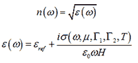
where σ(ω,μ,Γ1,Γ2,T) is calculated as described in Eqn. 1 of Ref[1]. Note that εref is the permittivity of free space for the isotropic graphene model and the permittivity of free space for the out-of-plane direction for the anisotropic graphene models. Please refer to sections C.E.7 and 8.K in RSoft CAD manual for additional background information.
The RSoft Material Editor includes several built-in graphene models. They can be found in the Special group under the RSoft Libraries group as shown in Fig. 1.

Figure 1: Graphene Material in Material Editor Table
The graphene material is isotropic while the GrapheneCX, GrapheneCY, and GrapheneCZ materials are anisotropic. The name of the anisotropic materials denotes the out-of-plane or "stacking" direction: for example, GrapheneCY is oriented so that the graphene layer is in the XZ plane. In general, the isotropic graphene model is preferred, but depending on your polarization and graphene orientation, it may be necessary to use one of the anisotropic models.
Each design file can combine multiple graphene models, each with different properties. To use a specific graphene model in your design, drag the desired model to the Project Materials group. Once here, the specific properties and name of your model can be set in the special Semiconductor Parameters symbol table, accessed in the Semiconductor tab of the Material Editor. Click Edit Table on the Semiconductor tab to change these values, as shown in Fig.2. Note that these material models are based on the graphene_real() and graphene_imag() functions described in the previous section.

Figure 2: The Semiconductor Parameters symbol table
The table below details how the capitalized local variables correspond to the arguments of the graphene() functions described in the previous section:
|
While the built-in material uses reasonable default values for these parameters, it is critical that you use values that correspond to your specific situation.
The optical properties of graphene at a temperature T of 300K, a scattering rate Γ of 5meV, and a thickness H of 0.7nm are shown in Fig. 3 [2]. Fig.3a is obtained by using graphene material in the Material Editor and displaying permittivity vs. wavelength at three chemical potential values. Fig.3b is obtained by defining the graphene function in the Symbol Table, performing a Symbol Table scan in MOST vs. chemical potential, and then calculating dielectric constant using metrics in MOST. The dip in the curve of the dielectric constant magnitude shown in Fig. 3b indicates the point at which “metallic graphene” transforms to “dielectric graphene” where the real part of εeff is 0. In this case, the “transition chemical potential” μt equals 0.515eV.
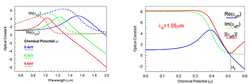
Figure 3: Optical properties of graphene for T=300K, Γ=5meV, and H=0.7nm:
a) The effective dielectric constant (real part, imaginary part) as the function of wavelength at three chemical potential values and b) The effective dielectric constant (real part, imaginary part, and magnitude) as the function of chemical potential
at λ0 =1550nm.
References


