
Synopsys Cloud
Cloud native EDA tools & pre-optimized hardware platforms
Request a Free Trial →
Optical modulators are essential components for the transmission of information through optical fibers. An optical modulator with Mach-Zehnder interferometer structure can be driven by either a lumped electrode or a “travelling wave” electrode. The RC time-constant of the lumped electrode can limit the speed of operation of the modulator. In the travelling-wave design, the electrode is designed as a transmission line. Hence the electrode capacitance is distributed and higher modulation speeds can be achieved.
The 2015.06 version of OptSim™ Circuit, an RSoft™ Photonic System Design Suite product, adds electrical and optical circuit elements required to design a photonic integrated circuit (PIC) of the travelling wave Mach-Zehnder modulator (TW-MZM).
The layout, as shown below, comprises of bidirectional PIC elements such as two traveling wave optical phase shifters, optical splitter 1x2 and combiner 2x1 with user-defined power ratio.
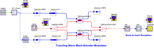
Layout of a Traveling Wave Mach-Zehnder modulator PIC with microwave circuit connecting the electrodes to the generator and load impedances
Each traveling wave phase shifter has an optical waveguide and a surrounding electrical transmission line introducing change in waveguide’s refractive index and propagation loss. The interaction between the electrical and optical signals is distributed along the propagation direction [1]. Thermal behavior of the waveguide (and hence modulator) is modeled via derivative of effective index and propagation loss as functions of temperature.
The layout above also includes a microwave circuit for the traveling electrodes connections composed of a transmission line, a first impedance mismatch between the generator and the phase shifter electrode, and a second impedance mismatch between the phase shifter electrode and the load.
When there is no mismatch between the impedances of the generator, travelling wave electrode and load, there are no electrical reflections and the back-to-back received eye is wide open:
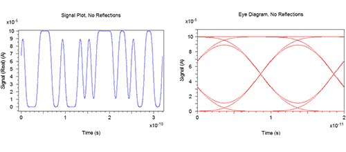
Back-to-back received signal and eye diagrams with no impedance-mismatch
However, when there’s a mismatch between the impedances of the generator, travelling wave electrode and load, the impact of the electrical microwave reflections originating from the load to the circuit performance are pronounced well:
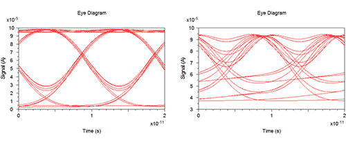
Back-to-back received eye diagrams with (left to right) increasing impedance-mismatch
The performance of the TW-MZM also depends on the matching between the effective index of the optical waveguide and the electrical transmission line. A similar analysis using OptSim Circuit would show that ideal matching results in nearly infinite bandwidth while even a small mismatch (say, 10%) can adversely affect the performance.
For more information, please contact rsoft_support@synopsys.com.
References
[1] K. Zu, V. Saxena, X. Wu, and W. Kuang, “Design considerations for travelling-wave modulator-based CMOS photonic transmitters,” IEEE Transactions on Circuits and Systems – II: Express Briefs, vol. 62, no. 4, pp. 412-416, April 2015.
Learn about the new features in the latest version of OptSim, OptSim Circuit and ModeSYS™ by watching our videos. The videos, as well as other resources, are available on our Customer Support Portal.
This 3-minute video provides an overview of transmitter and receiver models for PM-8QAM systems in OptSim v2015.06 and demonstrates design of a PM-8QAM system via an application note.

This 2-minute video provides an overview of the DSP library for MATLAB in OptSim v2015.06 and demonstrates its use.

This 2-minute video provides an overview of the IMEC PDK elements and travelling wave circuit models in OptSim Circuit v2015.06. The video also demonstrates analysis of photonic chip’s performance bounds and yield via Monte Carlo statistical scans.

This 2-minute video provides an overview of the Gloge power-flow equation based on the large-core multimode fiber model in ModeSYS v2015.06 and demonstrates design of a 1-mm step-index fiber-based link via an application note.


